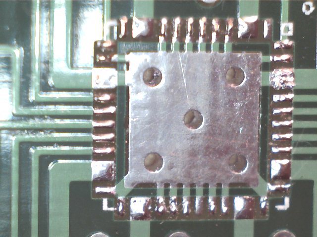
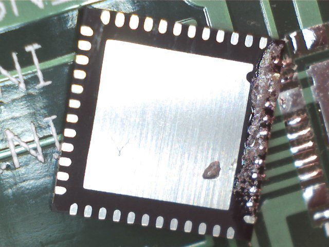
 It is indeed possible to succesfully solder small VQFN packages with a limited number of tools and without hot air. It appears the guide we linked too the other day is currently down however we will be posting our own abbreviated guide in the very near future. We used a few simple, relatively cost effective tools:
- Fine tipped soldering iron (we used a simple atten soldering station)
- Solder paste
- Tweezers
- Tissues (lint free cloth would be better)
- Isopropyl alcohol
- Solder wick
- Microscope ($30 USB variety works fine)
- Reflow controller prototype
- Thrift store frying pan
- continuity tester
The process is relatively straight forward however time consuming, a little luck doesnt hurt either. The basic principle is to apply a little solder to all pads, both on the chip and the pcb so when the boards reaches a reflow temperature all of the pads have the required ammount of solder and there is no paste on the soldermask to potentially cause shorts. The one exception is any thermal pads in the middle of the chip, they should just have solder applied on the chip, not the PCB. This was easier to apply directly with wire solder, simply apply enough to ensure the whole pad is covered but not buldging, looking side on should show a very small rise in the centre.

The guide we linked to recomended tinning a soldering iron then transfering this to the pad when it is heated. We found this process to be very hit or miss so instead we worked with solder paste. A thin smear of paste over a line of pads then moving over the pads with the iron melting the solder and ensuring it beads onto the pads. Then wipe away the excess with a cloth and alcohol. Whilst this sounds relatively straight forward any mistakes can be time consuming to clean up. A microscope allows you to get a clear view of the surfaces and check that each pad has some solder (you dont want it flooded as it is likely to cause a short later).

The next step is to reflow the board. This is where you may need hot air if you are just working on the one board component. In our situation we were working with a virgin board and this was the most complicated component (the other are mostly 1206 package passives) so we alligned the package (another time consuming task) ensuring that all pads were alligned on all sides within half a pad. This we inspected with the microscope and nudge appropriatly. Next time we repeat this process we would probably use a compong like Blu-Tak to apply a small adhesive force and stop the component moving too much when nudged. Finally reflowing the board to set the solder, a few small nudges during the reflow stage should ensure the part is properly alligned and reflowed as it snaps back into place.
From here most of the work is done, final checking and some additional soldering if required. We found that solder wick can remove brdiges provided they are external and accesible. Power pins had a little extra solder applied to them using the tinned iron method and all pins were tested for shorts with a continuity meter. The probes on my meter were not fine enough for my liking, dulled from years of use. Instead a small piece of solid wire cut at an angle and held in aligator clips workes very well.
