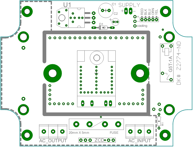
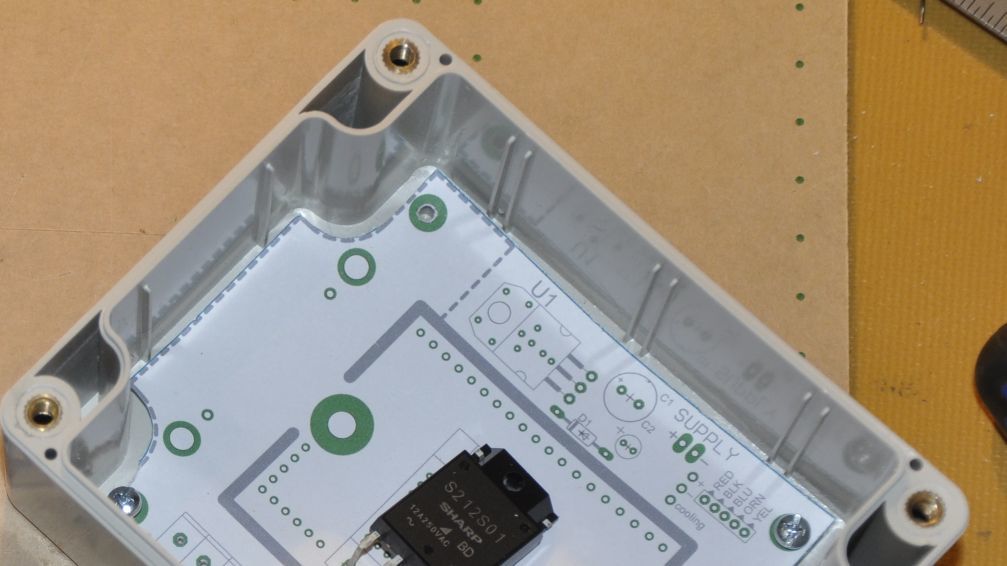
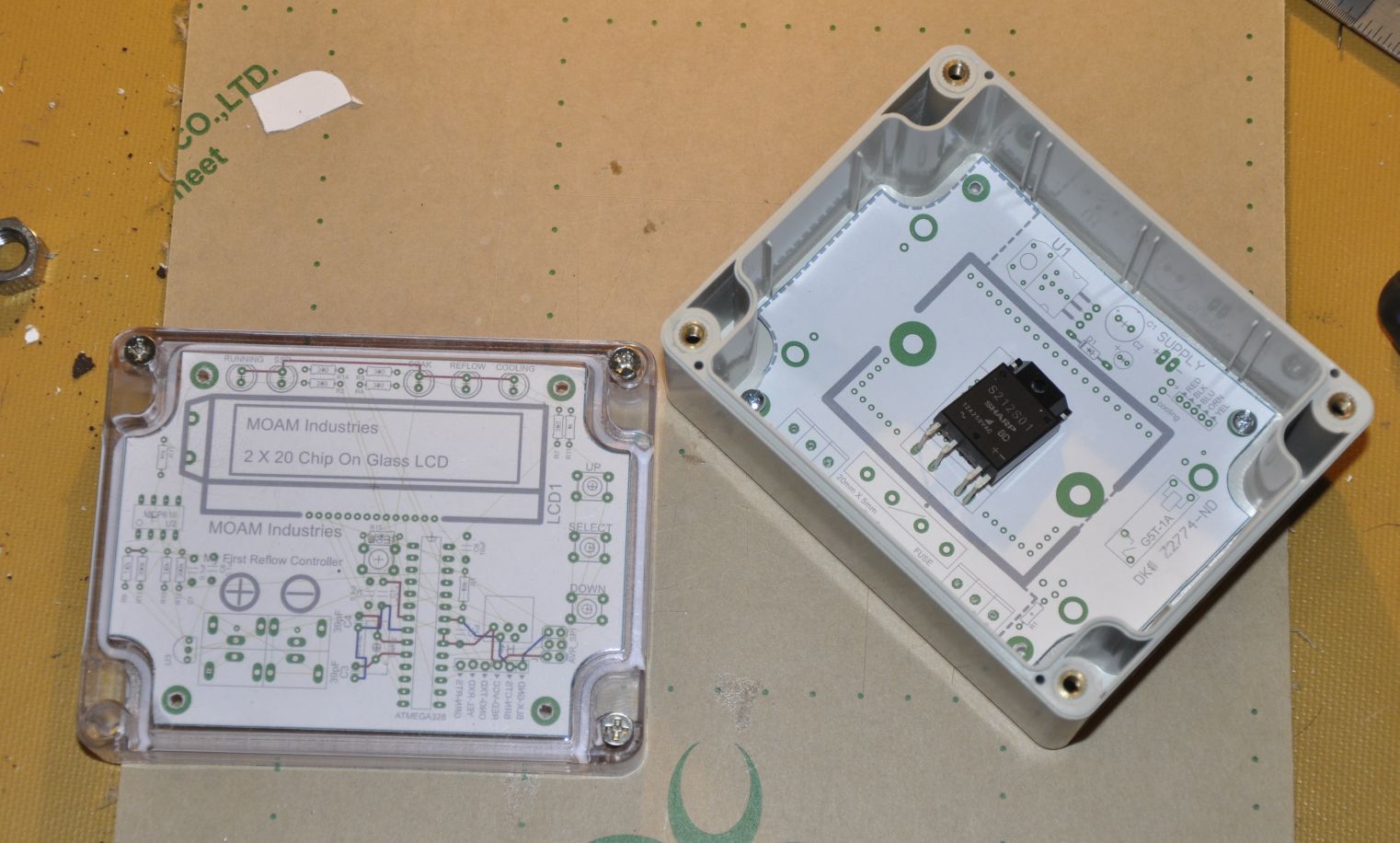
As we move towards the final version of our reflow controller kit we needed to test the mechanical fit of our boards. This ensures that all of our holes are alligned properly, and components fit with the appropriate clearance. This is a really useful step because when you are working on a screen where sizes can be blown up 1,000% what appears to be adequte clearance can easily be misrepresented. With Eagle the easiest method is to select the appropriate layers. Typically tPlace, bPlace, Milling, tNames, bNames, pads, vias and holes. This ensures all of the mechanicaly important layers are visible whilst the traces are not, they typically confuse and over power the drawing.  To output the drawing simply use the print function under File>Print. Ensure the scaling is set as 1 then select your output destination. As our printer is not connected to our development machine (long story) we output the file to a PDF then print from a laptop (again ensuring that no scaling or “fit to page” are selected). The next step is brought to you by your year 6 craft teacher and all the training she provided in cutting along the lines. Scalpels are the easiest way to cut along compond curves and also make it easy to cut out the associated holes.
  Doing this process really helps you get a feel for a PCB without spending hundreds on prototype boards, it also helped us pick up an issue with our enclosure. When we ordered our checked the sizing was appropriate with a drawing provided by the manufacturer. Off this drawing we designed all of our mechanical fixing points, as it turns out the drawing from the supplier was out by almost 2mm in one dimension which pushed all of the bottom fixture points out. By working through this process we picked up a potentially costly mistake and got a better feel for our product. As a final note this method is also useful for checking the allignment of other fixtures such as voltage regulators, our solid state relay and header terminals.

