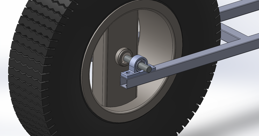
Whilst you could spend years of your life studying the fine details bending at Mars U alongside Bender Bending Rodriguez, even a little basic mechanical engineering can save you a lot of hassle down the road. So this post looks at how to size the main drive shaft and what effect the forces on the system will have.  The entire load of the roach bot will rest on three points, the two front wheels and the large rear wheel. The rear wheel is already very heavy. However there is still a lot of weight to be added to the system:
- 125cc engine for rear wheels
- batteries
- compressor
- brake system
- computers
- support frame
- Exoskeleton
- A person?
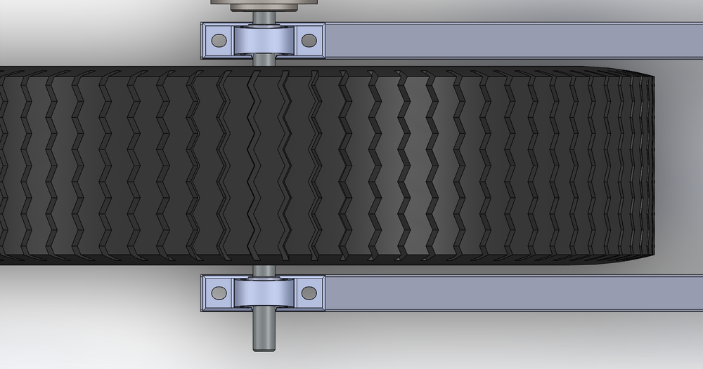
The load on the rear axle could easily approach 300-400kg, at rest this is a ~3000-4000N on the center of the axle. When you consider additional shock impacts as the robot drives over bumps or through ditches a total load on the axle could approach 5000N somewhat frequently. As the roach will steer with the front two wheels the big wheel will simply rest on two wide inner ring bearings mounted in pillow blocks. In an ideal world I would have a complete system design with accurate loads and mass distribution, in the interest of “getting things done” I have made some rough assumptions that leave me with a suitable margin.


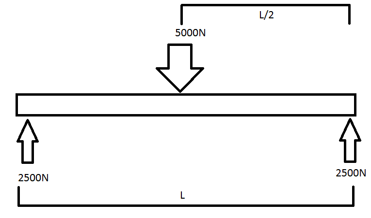
The Maths Whilst i could be safe to assume a 50mm diameter solid steel shaft would easily support the load it is not the most cost effective, nor is it a clean technical solution. Therefore the first step in an engineered solution is to determine the forces acting on the system. To make the diagrams a little easier to comprehend and typical of most free body diagrams [FBD] I have inverted the forces. The position of the wheel provides a central point load approximated earlier whilst the bearings provide an equal reaction force.  Simple free body diagram of shaft with central point load and reaction forces at the bearings Thankfully the system is fairly simple, as bending calculations for multiple loads can quickly get complex and as someone who feels much happier with electronics they get a little scary. It is worth mentioning that many popular cad programs can do basic static load analysis with assessment of deflection, factor of safety and detailed stress maps. However it doesn’t help to build the base knowledge and they can often be fiddly to setup with simple round shafts. With the loads identified the next step is to find a deflection formula that suits this scenario. Many mechanical engineering textbooks associated with static loads and mechanical modeling will have simplified equations for common scenarios. I would also recommend this set of lecture slides which has valuable information of the modelling of shafts.
  Now we have most of the information. We are not building a race car where everything needs to be lightweight, nor is the shaft too long, so using steel for the shaft is not a problem. The modulus for steel is derived directly from a table. From dimensions taken of the wheel and modeled in CAD the length is also known. The only remaining unknown is the inertia of the shaft. Inertia is calculated from several other equations and varies based on the distribution of mass of a spinning object. In this application we have two separate formulas to work with. Hollow or solid shafts. We may be able to save material costs by using a larger hollow shaft than a smaller solid shaft. Also given the scale of the project a larger shaft can be a little easier to handle as well as giving the machine a ‘beefier’ aesthetic.
  Inertia formula for solid and hollow uniform shafts With all of the information now available, a spreadsheet to compare different shaft diameters with the resulting deflection makes the decision trivial but well informed. From this data I can see that a 30mm diameter shaft will have a suitable level of rigidity and will have minimal angular deflection at the bearings [this formula was derived from the lecture slides linked to above]. Even with a 25mm center bore the deflection is less than a mm. However a 2.5mm wall thickness will not be suitable for mounting shaft keys. Deep groove ball bearings are sufficient as there is no axial loads, nor are the loads so high that roller bearings would be required.
