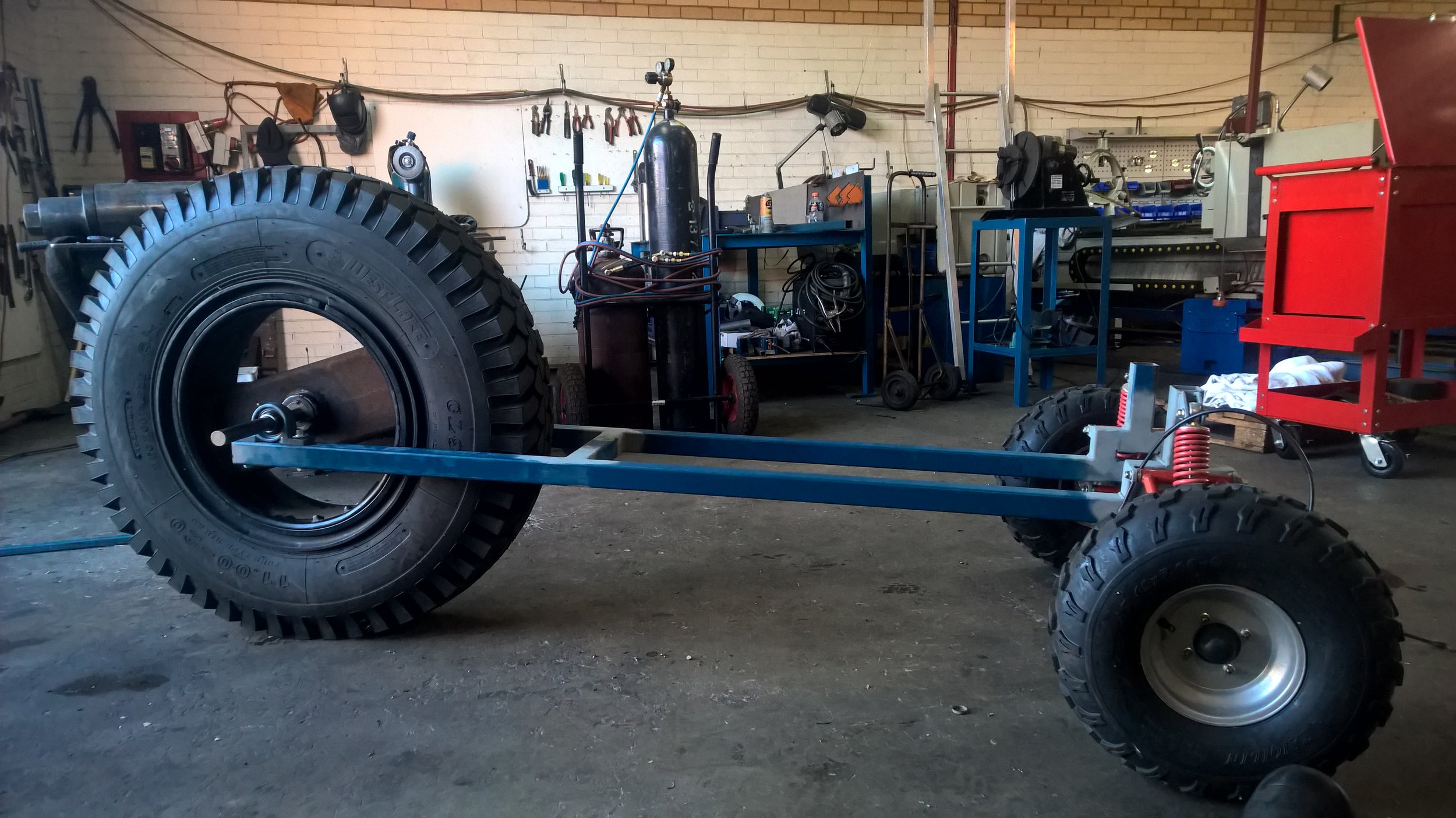
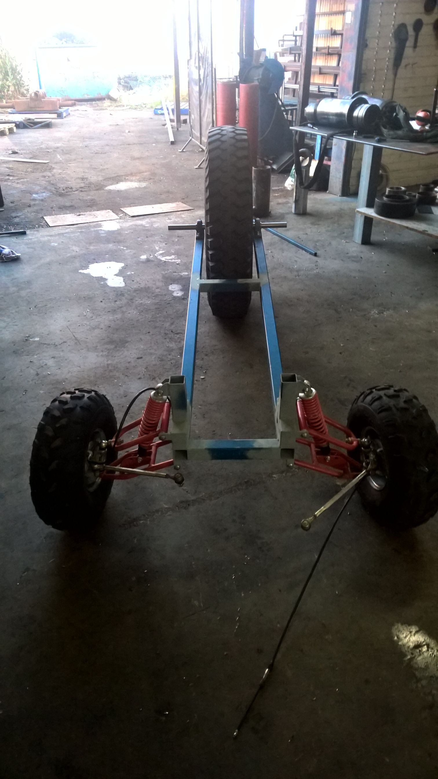
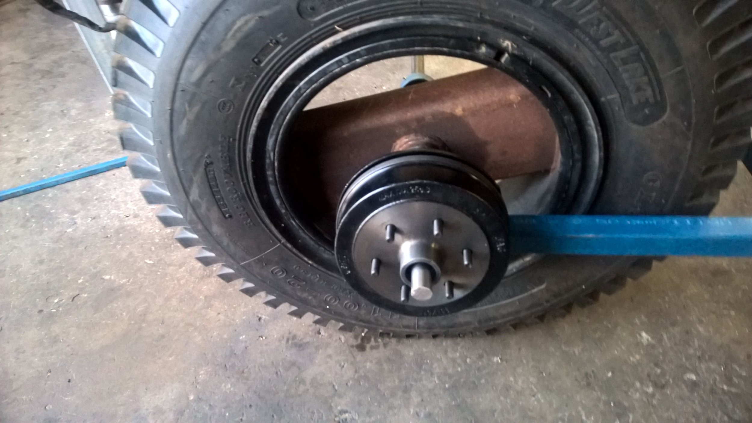
The robot finally has some structure! Over the last few evenings and some half weekends the base frame has been assembled. Almost entirely built on 50x50x2.5mm Square Hollow Section (SHS) it is nice and rigid. The front suspension and tyres were salvaged from the quad bike that also donated the 125cc motor for the rear drive. The main arms are 2m long which gives the machine a long stance although possibly still rather short compared to the reference image. The suspension is also stockier than the wider and spindly feel from the reference image so some of this will probably need to be reworked in the future. The main objective of the machine in this state is to serve as a development platform for the robotics and control system. Once that has been proven I can look at rebuilding the assembly for a more artistic aesthetic. The Next steps: Steering, brakes and propulsion. Originally I had planned to work on the drive first but the front wheels really need to point in the same direction to begin with. This will most likely be a modified rack and pinion with a servo drive. The robot finally has some structure! Over the last few evenings and some half weekends the base frame has been assembled. Almost entirely built on 50x50x2.5mm Square Hollow Section (SHS) it is nice and rigid. The front suspension and tyres were salvaged from the quad bike that also donated the 125cc motor for the rear drive. The main arms are 2m long which gives the machine a long stance although possibly still rather short compared to the reference image. The suspension is also stockier than the wider and spindly feel from the reference image so some of this will probably need to be reworked in the future. The main objective of the machine in this state is to serve as a development platform for the robotics and control system. Once that has been proven I can look at rebuilding the assembly for a more artistic aesthetic. The Next steps: Steering, brakes and propulsion. Originally I had planned to work on the drive first but the front wheels really need to point in the same direction to begin with. This will most likely be a modified rack and pinion with a servo drive. From there, being able to stop the machine when(if) it takes off is also more important than the drive system so the brakes need to be mounted and a controller designed for them. Currently I expect to use an electronic trailer drum brake on the rear axle. This system will be challenging as I dont expect the brakes to have a good static braking force, instead they rely on the dynamics of the moving hub to apply braking force. However at $100 it is worth attempting this method before complicated and expensive hydraulic setups.
 From there, being able to stop the machine when(if) it takes off is also more important than the drive system so the brakes need to be mounted and a controller designed for them. Currently I expect to use an electronic trailer drum brake on the rear axle. This system will be challenging as I dont expect the brakes to have a good static braking force, instead they rely on the dynamics of the moving hub to apply braking force. However at $100 it is worth attempting this method before complicated and expensive hydraulic setups.
  As for propulsion….. I want to model the system a little more before I take this step. Some quick calculations are showing me that the rear sprocket may need to be as large as 600mm in diameter. From 8mm plate to suit the 428 chain sprocket the motor came with this could be very expensive to have laser cut. So instead I want to model the inertia of the main shaft and try to characterise the motor performance a little before I commit to this step.
